

This Side-View Kit Installation Guide provides a detailed, step-by-step tutorial for installing the CamRescue Side-View Kit. Visit CamRescue to explore our range of products and find the perfect fit for your needs.
Table of Contents
Why We Call it Side-View Kit
Our Side-View Kit earns its name for its specialized role in seamlessly replacing dead side cameras within small vehicles’ 360 Bird View systems.
Equipped with an ultra-wide-angle lens and a specially designed housing, this kit is a pro-grade solution for replacing malfunctioning side view cameras.
Featuring 10 formats in 1 camera and an easy-to-use format switching button, it provides a smooth installation experience and ensures optimal effects.
With its ability to maintain clear and reliable side views, this kit enhances visibility and safety on the road.
In other words, when you need to fix your vehicle’s dead side view camera, this kit is the solution.
For other specific camera requirements, please choose:

Front-Back Kit
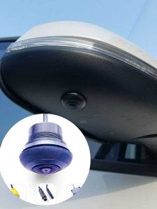
Front or Back Cameras for 360 Bird-View Systems
Universal Kit
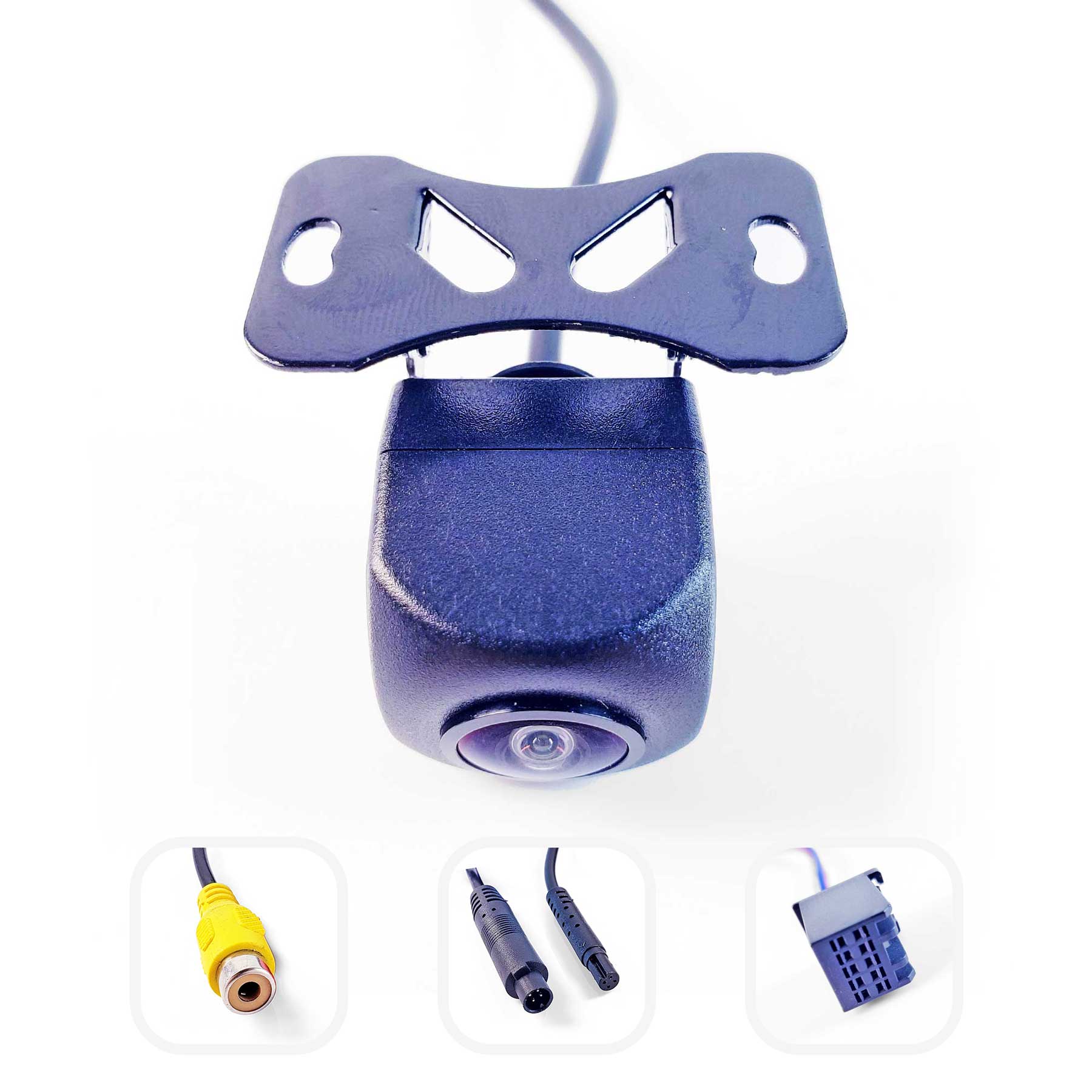
Backup Camera for Cars, SUVs and Mini Vans
Inside the Box
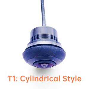
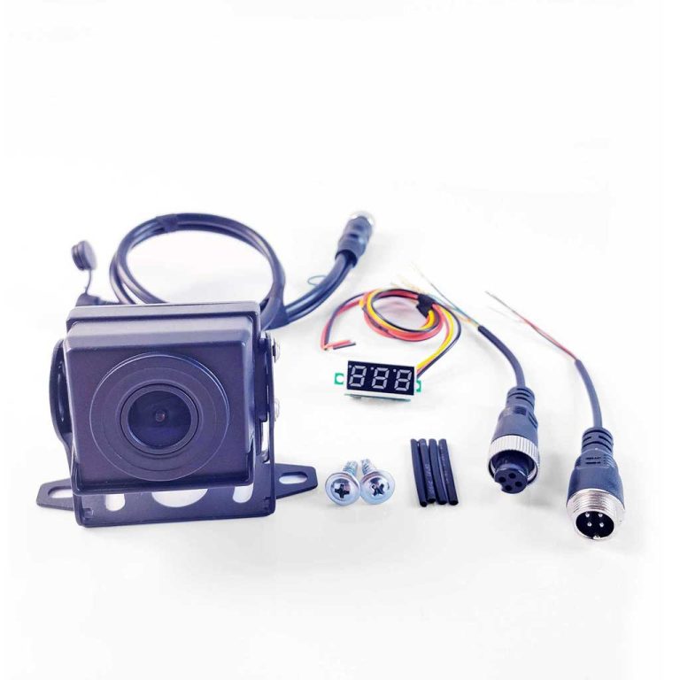
The Side-View Camera T1: T1, a Cylindrical Style Housing universal camera, equipped with a 220° wide-angle lens (fisheye lens), comes with a convenient physical format switching button placed in the middle of the cable. Switching to the next format is as easy as a long press for about 7 seconds.

The Side-View Camera T2: T2, a Bevel Style Housing universal camera, equipped with a 220° wide-angle lens (fisheye lens), comes with a convenient physical format switching button placed in the middle of the cable. Switching to the next format is as easy as a long press for about 7 seconds.
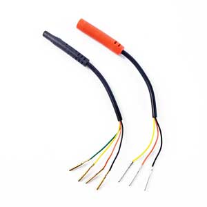
4-PIN Breakout Cable (Male/Black): A dash cam 4-PIN male connector that converts to four separate sub-cables (with pins).
4-PIN Breakout Cable (Female/Red): A dash cam 4-PIN female connector that converts to three separate sub-cables (with pins).
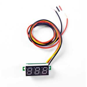
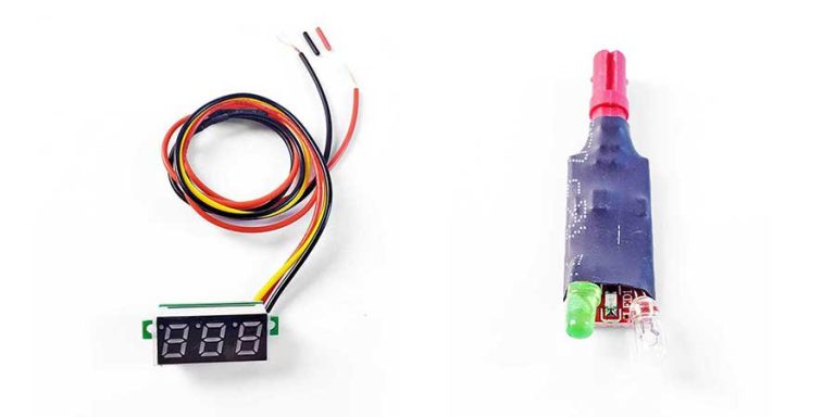
Cable Voltage Tester: Use this voltage tester to identify the correct power supply cable among the sub-cables.
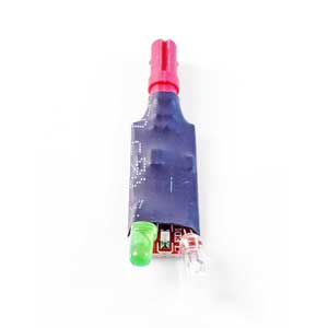
Cable Definition Validator: The LED lights on this indicator inform you whether the sub-cable sequence (DC input) is correct or not.
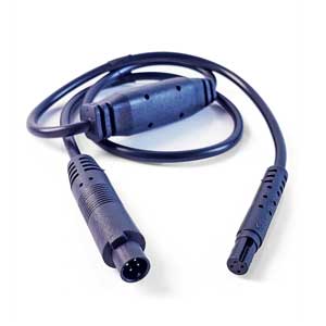
Step-Down Cable: This cable steps down 5V to 36V input to a 5V output. Use this step-down cable when the power input of your device is higher than 5V.
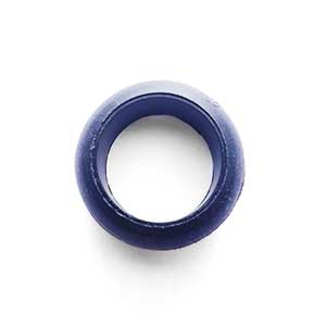
Silicone Gasket: The Silicone gasket is used to fix the T1 or T2 camera to the round hole on the reversing rearview mirror.
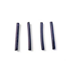
Heat Shrink Tubes: Used to protect the joints of the 4-PIN Breakout Cable. Heating causes them to shrink.
Good to Know Before Installing
A. Fool-proof design on dash cam 4-PIN connector.
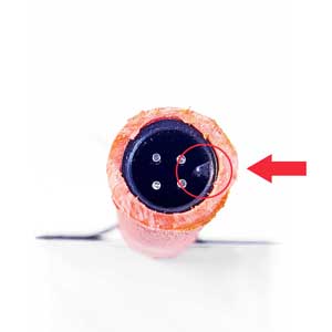
① Cut to show the fool proof design inside 4-PIN connector
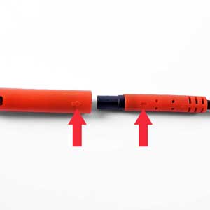
② So align these two arrows together when connecting
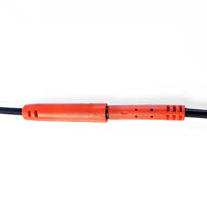
③ Dash cam 4-PIN connector well connected
Are there a fool-proof desgin in the RCA connector? No, it’s just a plug and play game.
B. No standardized PIN/sub-cable sequence for 4-PIN connectors in the market.
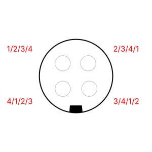
For unsure situation, use the Cable Voltage Tester to confirm the sequence—inserting connectors recklessly may damage the camera, main unit, or even the vehicle’s electrical system. Play the 4-PIN connector plug-and-play game only after confirming the sequence.
C. When testing the cameras in the 360 bird view system, you can typically access the front, rear, left, or right camera displays through the system menu on the host radio.
D. Turning the key to ACC mode can power the head unit without starting the vehicle.
E. The vehicle can be shifted into reverse gear with the key in ACC mode and the handbrake engaged.
The Side-View Kit Installation Guide
In general, most aftermarket 360-degree bird view systems on the market utilize dash cam 4-PIN connectors, with few or no RCA connectors or other types. Therefore:
- Installing the camera in this Side-View Kit follows essentially the same process as installing the Universal Kit.
- Before testing the camera image, please review the Test Notes for the Side-View cameras.
Quick Guide:
- If it’s a Dash Cam 4-PIN connector case: Connect the 4-PIN Breakout Cable (Male/Black) to the 4-PIN extension cable’s connector and use the Cable Voltage Tester to confirm the function of the 4-PIN Breakout Cable’s pins. Please follow the 4-PIN Installing Guide.
- If it’s a RCA or other unkown connecters case: Cut off the tail cable of the original dead camera, keeping the end with the connector intact. Separate all the sub-wires of this connector to prevent any short circuits. Reconnect this connector to the extension cable, then test and confirm the functionality of each separated sub-wire. Please follow the Original Factory Connector Installing Guide.
4-PIN Installing
Guide in Brief:
- Connect the 4-PIN Breakout Cable (Male/Black) to the 4-PIN extension cable’s connector.
- Use the Cable Voltage Tester to confirm the function of the 4-PIN Breakout Cable’s pins.
- Connect the positive to the red sub-cable, negative to the black sub-cable, and the signal to the yellow sub-cable on the 4-PIN Breakout Cable (Female/Red).
- Connect the camera to the 4-PIN Breakout Cable (Female/Red).
If the extension cable’s connector differs from the tutorial, follow these steps: Cut the old cable of the dead camera, separate the sub-cables, and reconnect it to the head unit’s extension cable. Test each sub-cable, identifying the Positive, Negative, and Signal. Connect them to the 4-PIN Breakout Cable (Female) accordingly. Red to positive, black to negative, and yellow to signal.
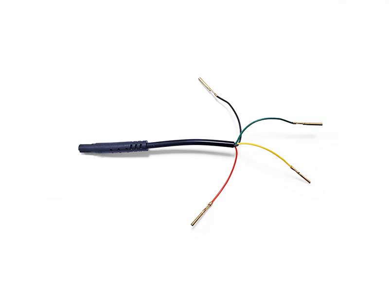
Step 1:
Separate each sub-cable before plugs the 4-PIN Breakout Cable (Male/Black) into the 4-PIN connector.
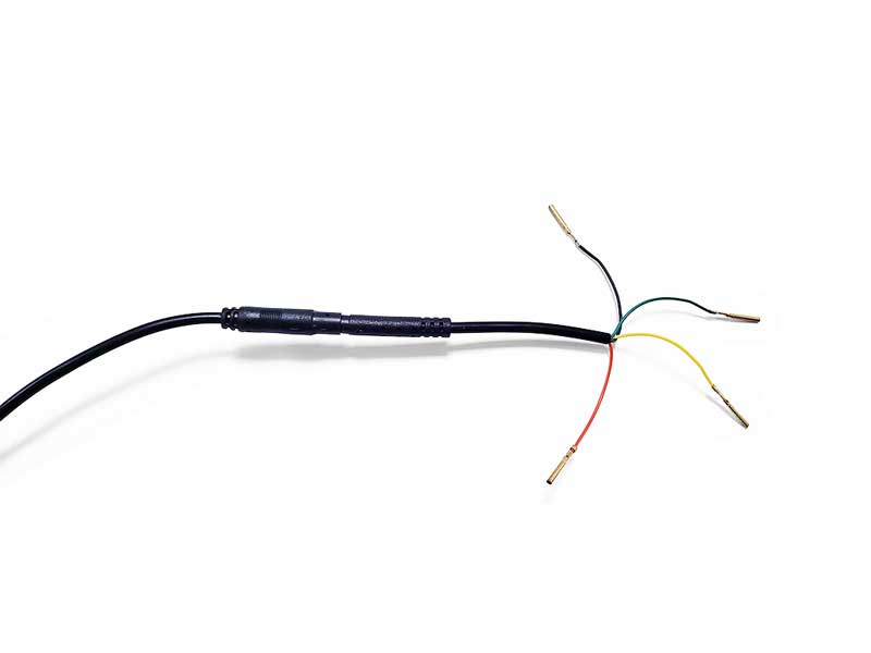
Step 2:
Connect the 4-PIN Breakout Cable (Male/Black) to the 4-PIN extension cable’s connector.
Step 3:
Use the Cable Voltage Tester to confirm the definition of the 4-PIN Breakout Cable’s pins.

In this case, we confirm that the yellow wire functions as the positive cable.
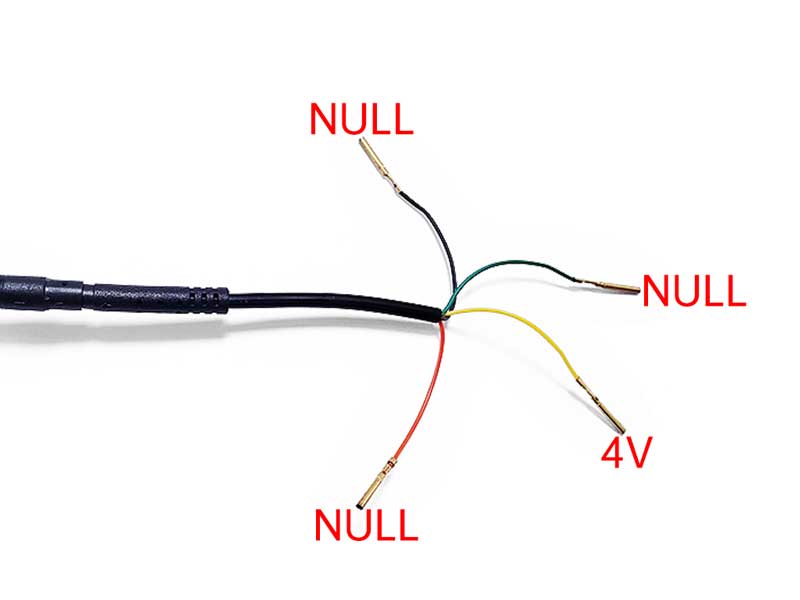
And then, we have the black wire = 3.3V, the red wire = 3.2V and the green wire = NULL.
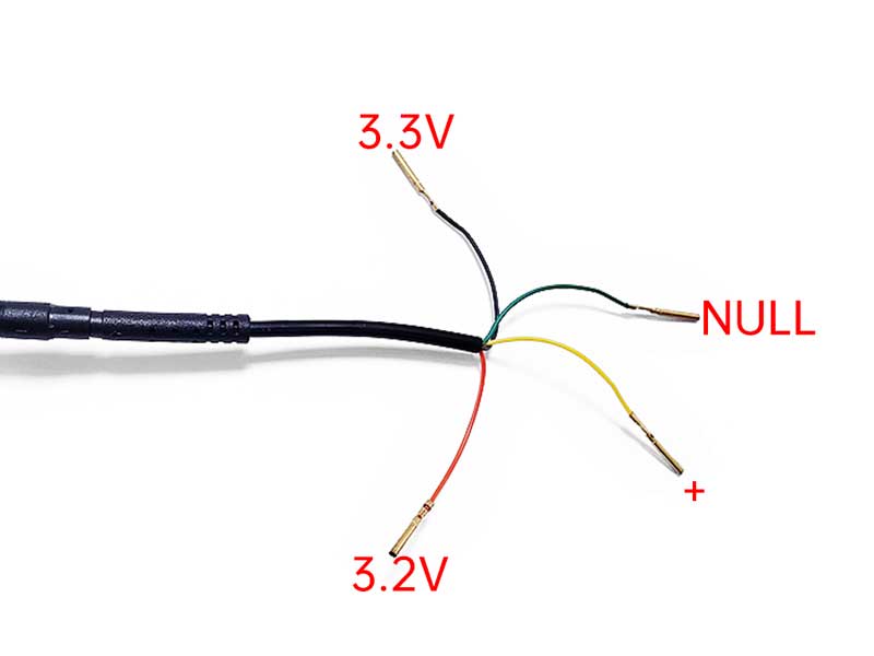
According to the usage guide of Cable Voltage Tester, we can know that the balck wire is the positive cable, the red wire is the signal cable, and the green wire is of no use to us.
Cable Voltage Tester Guide
Step-by-step tutorial for confirming voltage and function of each sub-cable.
Step 4:
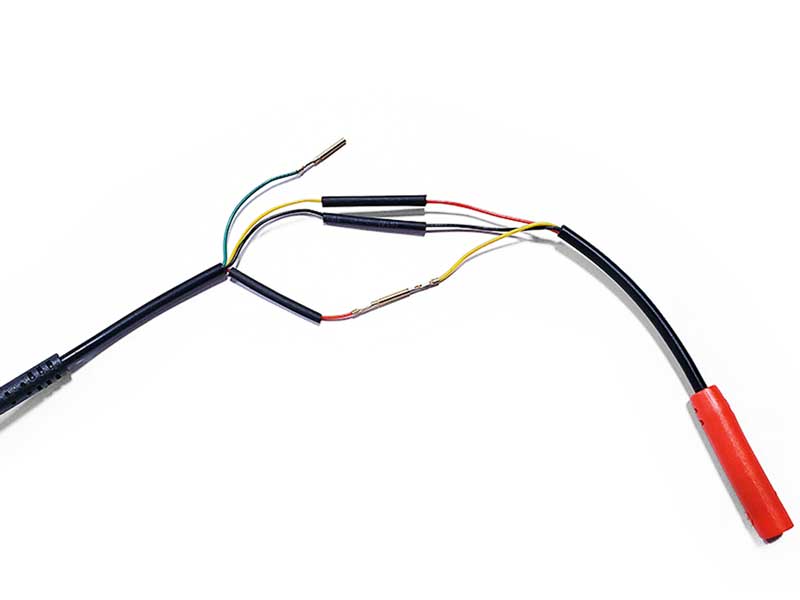
Connect the positive to the red sub-cable, negative to the black sub-cable, and the signal to the yellow sub-cable on the 4-PIN Breakout Cable (Female/Red).
Exercise caution while wiring to prevent wires from touching. Use heat shrink tubing to shield them from unintended contact.
Step 5:
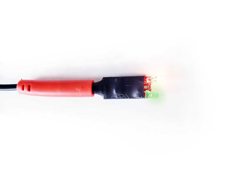
Connect the Cable Definition Validator to the 4-PIN Breakout Cable (Female/Red) to verify the correct confirmation of subcables.
Cable Definition Validator Guide
Know exactly what each warning light means.
If you encounter warning lights from the Cable Definition Validator, go back to Step 3 and ensure the correct definition of the sub-cables.
In our case, we have correctly connected the sub-cables and pins.
Step 6:
Now that we have correctly connected the sub-cables and pins, let’s plug the universal camera into the 4-PIN Breakout Cable (Female/Red) and check if the camera works as intended.
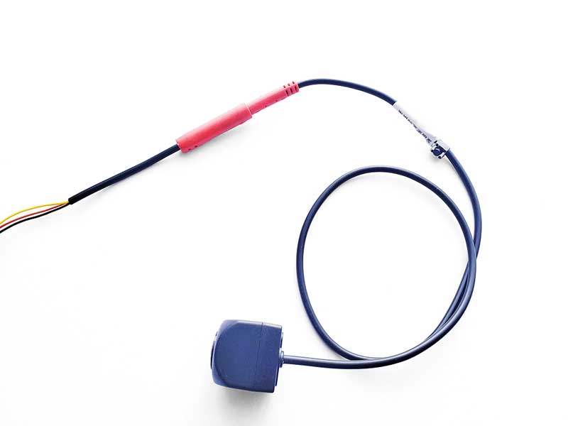
And now we can do the Camera Test.
Test Notes for Testing the Side-View Cameras
In the 360 Panoramic Bird View system, trigger wires are used to activate the left, right, or rear view cameras. Therefore, the key steps for camera testing are as follows:
- Set the key to ACC mode to power on the 360 Head Unit and determine the definition of the sub-cables.
- Connect the sub-cables and the camera correctly.
- Activate the Right Turn signal to test the Right side camera.
- Activate the Left Turn signal to test the Left side camera.
- * Shift the vehicle into Reverse Gear to test the rear view camera.
Yes, the camera should turn on when activated through the head unit menu option if it has been correctly replaced and the format matches. However, ensuring that the trigger signal is running properly is also essential.
So, before you put everything back, we recommend testing the corresponding side-camera when the corresponding turn signal is active.
What if the camera doesn’t works as expected?
!!! First of all, disconnect the camera, wait for 5 seconds, then reconnect it and test again. Sometimes, magic happens. If still not:
Issue 1:
Image Upside-down, Mirrored, Black and White Display, Flickering, and more…
HOW: This indicates an incorrect image format. To resolve this, long-press the Format Switching Button on the camera cable for about 7 seconds until the image appears correctly. The button allows you to cycle through 10 different formats by pressing it.
Issue 2:
No Power Supply.
HOW: If the Cable Voltage Tester indicates power supply, then power is available to the camera system. Not this one.
Issue 3:
Incorrect Trigger Wire Connection.
HOW: If you can activate the camera view through the 360 bird view head unit’s menus but don’t get the expected view when using the turn signal, it’s likely a trigger wiring issue. Vehicle wiring can be complex, so consider watching helpful videos on YouTube or seek professional assistance. Video FYI:
Or:
How to Connect – 360 Camera
Since we only offer replacement cameras, the trigger line should work on your vehicle for many years, we are only here to provide recommendations.
Issue 4:
Camera Burnout!
HOW: If the camera is burnt out, use the backup camera included in the kit for this IT HAPPENS situation. DO re-confirm the sub-cable definitions and wiring before connecting the backup side-view camera.
Issue 5:
Head Unit Malfunction!
HOW: If none of the above situations apply, the head unit might be malfunctioning. Check other cameras in the bird view system or contact the head unit’s seller for further assistance.
FAQ
Q: Will your 360 side-view camera work with all PANORAMIC 360 view systems?
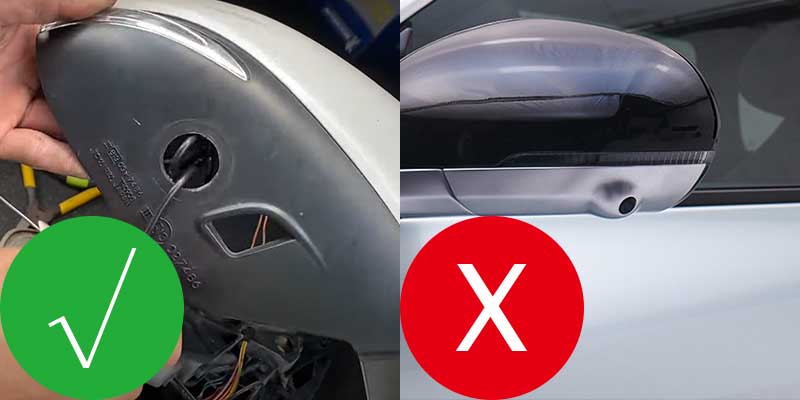
A: Our camera can work with various systems, but different housing designs may prevent installation in your vehicle’s rear view mirror. Before purchasing, ensure compatibility by checking the original housing design.
Q: My side-view camera is a factory OEM camera and it’s broken. Is your camera a suitable replacement?
A: Check the housing design of your factory OEM camera before ordering. If the housing is significantly different from ours, our camera may not be compatible.
If your vehicle has a circular hole installation style, our camera will work for you. However, if it has a completely factory OEM design, our camera will not be compatible with that installation style.
Q: What should I do if the 360 bird view image doesn’t automatically calibrate and appears distorted?
A: If your 360 head unit lacks automatic calibration functionality or manual calibation functionality, there’s nothing we can do to address this issue.
Q: The color of the image from your side-view camera looks different. Can it automatically adjust the color?
A: Our camera cannot automatically adjust colors. Every camera produces unique color effects, so it’s important to get accustomed to the new visuals.
Guide ends here, if you need further assistance, please don’t hesitate to contact us.