

This Heavy Kit Installation Guide provides a detailed, step-by-step tutorial for installing the CamRescue Heavy Kit. Visit CamRescue to explore our range of products and find the perfect fit for your needs.
Table of Contents
Why We Call it Heavy Kit
Our Heavy Kit is built tough for heavy vehicles like trucks, buses, and farm machinery. It replaces dead cameras with ease, ensuring reliable performance in rugged conditions. With its durable construction and versatile features, it’s the perfect choice for dependable camera solutions in heavy-duty applications.
Looking for solutions for small vehicle’s dead cameras Please choose:
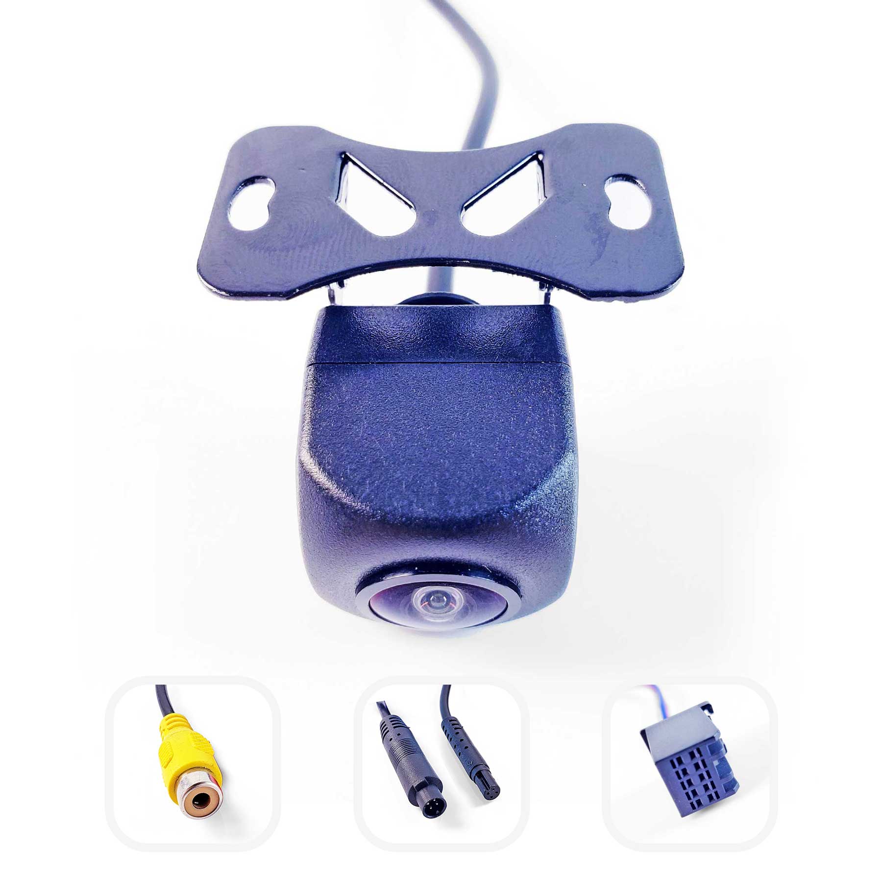
Universal Kit
Backup Camera for Cars, SUVs and Mini Vans
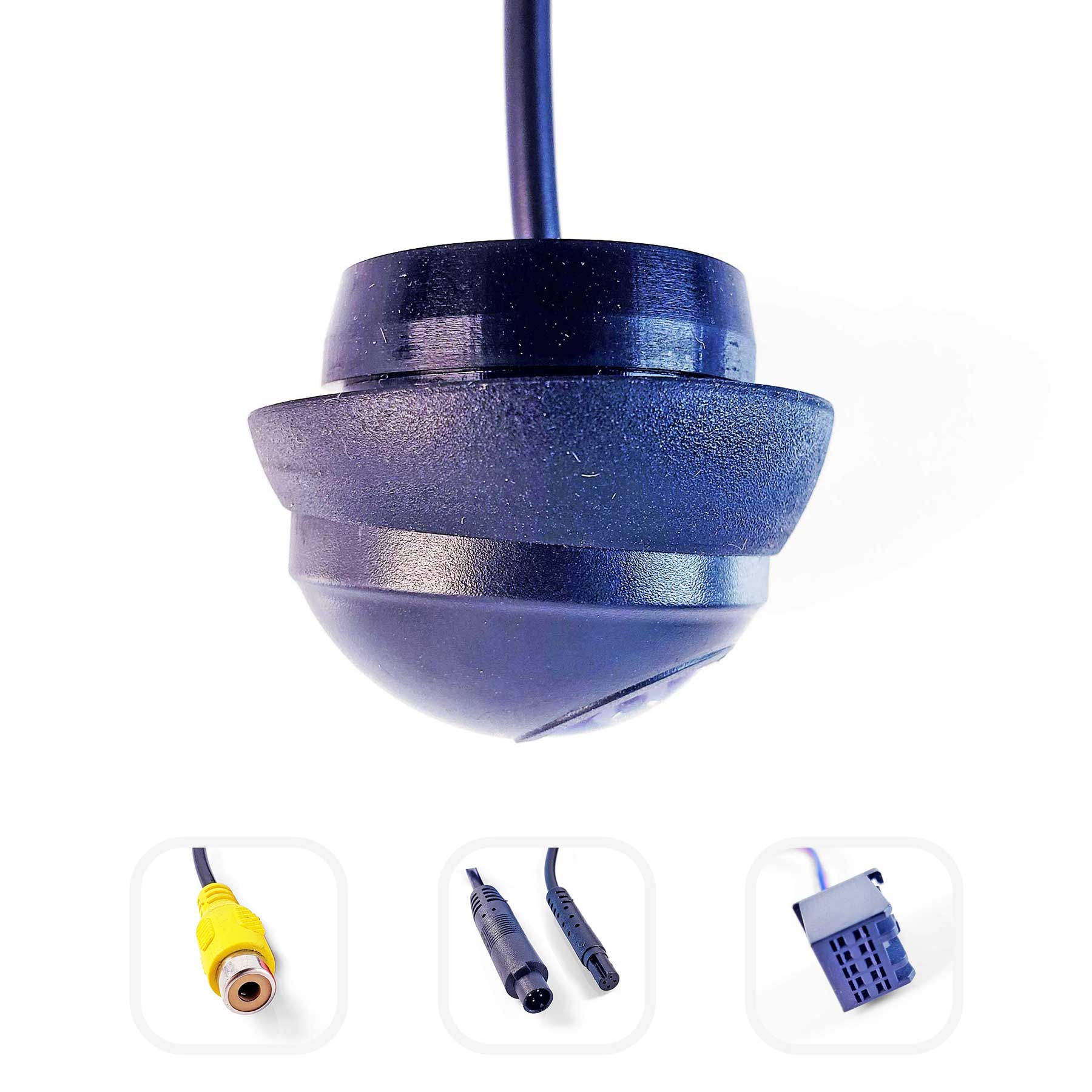
Side-View Kit
Side View Camera for 360 Bird-View Systems
Inside the Box
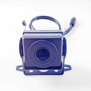
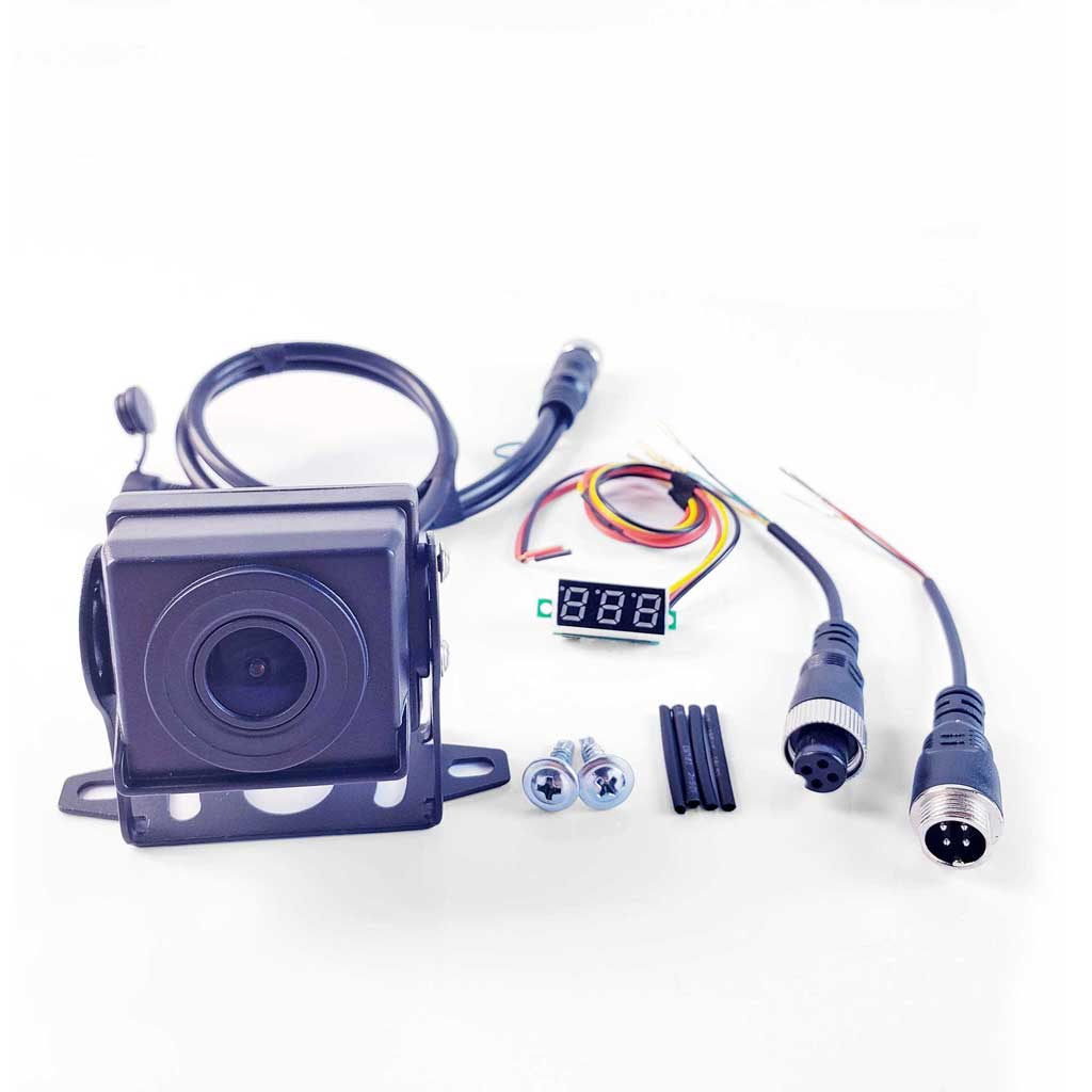
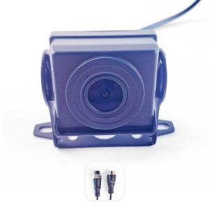
The Heavy Duty Camera: The heavy duty universal camera included in the kit, featuring a pre-equipped 4-pin male aviation connector. A physical format switching button in the middle of the cable allows you to switch to the next format by long-pressing for about 7 seconds.
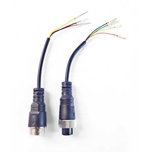
4-PIN Aviation Breakout Cable (Male): A 4-PIN Aviation male connector that converts to four separate sub-cables (with pins).
4-PIN Aviation Breakout Cable (Female): A 4-PIN Aviation female connector that converts to three separate sub-cables (with pins).
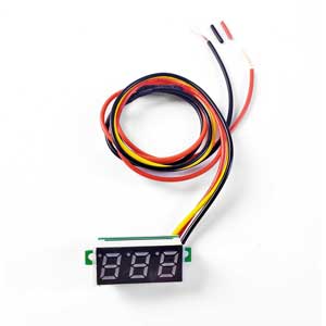
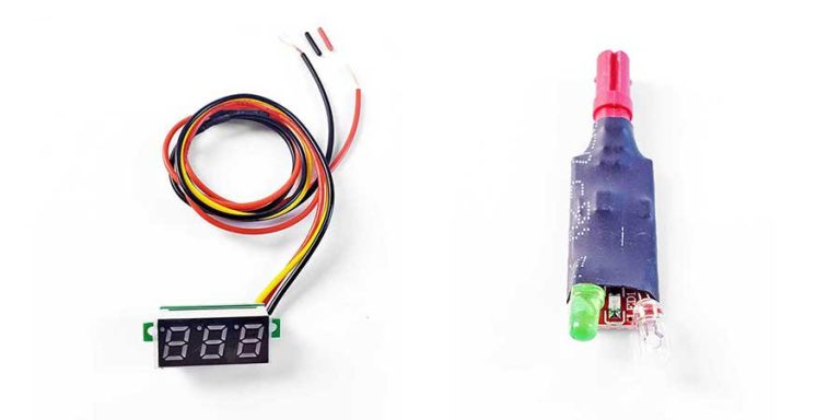
Cable Voltage Tester: Use this voltage tester to identify the correct power supply cable among the sub-cables.
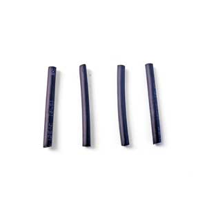
Heat Shrink Tubes: Used to protect the joints of the 4-PIN Aviation Breakout Cable. Heating causes them to shrink.
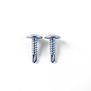
Screws x2: Used to fix the camera to the vehicle.
Good to Know Before Installing
A. Fool-proof design on Aviation 4-PIN connector.
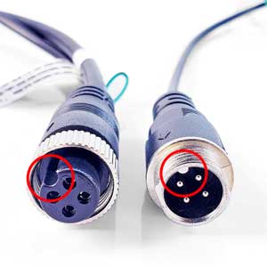
The fool-proof design is highlighted by the red circle in the image. The concave and convex parts must be aligned before they can be connected.
B. No standardized PIN/sub-cable sequence for 4-PIN Aviation connectors in the market.
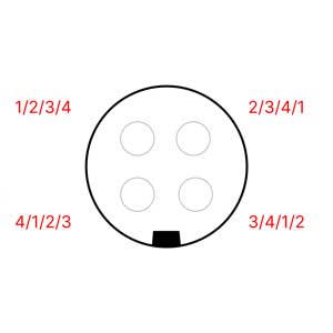
With the development of the market, although the definition of most aviation heads on the market is the same, but in fact, not all of them are. Our kit is prepared for these special situations.
For unsure situation, use the Cable Voltage Tester to confirm the sequence—inserting connectors recklessly may damage the camera, main unit, or even the vehicle’s electrical system. Play the 4-PIN connector plug-and-play game only after confirming the sequence.
C. Turning the key to ACC mode powers the head unit without starting the vehicle.
D. The vehicle can be shifted into reverse gear with the key in ACC mode and the handbrake engaged.
The Heavy Kit Installation Guide
Guide in Brief:
- Connect the 4-PIN Aviation Breakout Cable (Male) to the extension cable’s aviation connector.
- Use the Cable Voltage Tester to confirm the definition of the 4-PIN Breakout Cable’s pins.
- Connect the positive to the red sub-cable, negative to the black sub-cable, and the signal to the yellow sub-cable on the 4-PIN Aviation Breakout Cable (Female).
- Connect the camera to the 4-PIN Aviation Breakout Cable (Female).
Although dealing with a 4-PIN Aviation connector is like a simple plug-and-play game, but, the products on the market are very complex, and we still might encounter situations where the order of sub-cables are uncertain.
With uncertain pin definitions in each case, the Cable Voltage Tester becomes the key tool for success.
Step 1:
Separate each sub-cable before plugs the 4-PIN Aviation Breakout Cable (Male) into the head unit’s extension cable.
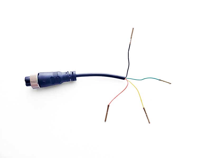
If the extension cable’s connector differs from the tutorial, follow these steps: Cut the old cable of the dead camera, separate the sub-cables, and reconnect it to the head unit’s extension cable. Test each sub-cable, identifying the Positive, Negative, and Signal. Connect them to the 4-PIN Aviation Breakout Cable (Female) accordingly. Red to positive, black to negative, and yellow to signal.
Step 2:
Connect the 4-PIN Aviation Breakout Cable (Male/Black) to the head unit’s 4-PIN extension cable’s aviation connector.
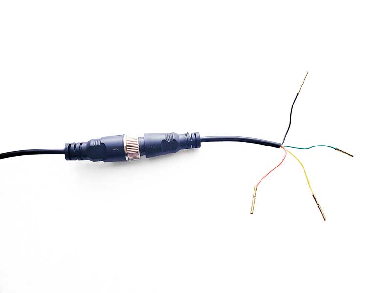
Step 3:
Use the Cable Voltage Tester to confirm the definition of the 4-PIN Aviation Breakout Cable’s pins.

In this case, we confirm that the yellow wire functions as the positive cable.
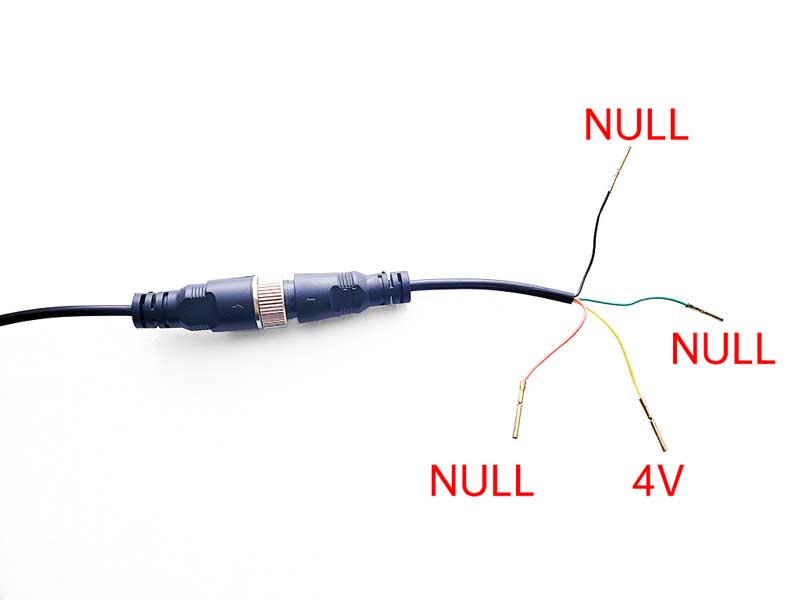
And then, we have the black wire = 3.3V, the red wire = 3.2V and the green wire = NULL.
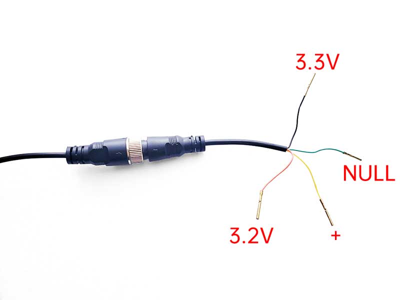
According to the usage guide of Cable Voltage Tester, we can know that the balck wire is the positive cable, the red wire is the signal cable, and the green wire is of no use to us.
Cable Voltage Tester Guide
Step-by-step tutorial for confirming voltage and function of each sub-cable.
Step 4:
Connect the positive to the red sub-cable, negative to the black sub-cable, and the signal to the yellow sub-cable on the 4-PIN Aviation Breakout Cable (Female).
Exercise caution while wiring to prevent wires from touching. Use heat shrink tubing to shield them from unintended contact.
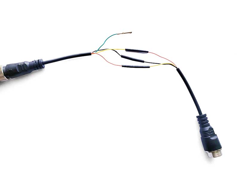
Step 5:
Now that we have correctly connected the sub-cables and pins, let’s plug the universal camera into the 4-PIN Breakout Cable (Female/Red) and check if the camera works as intended.
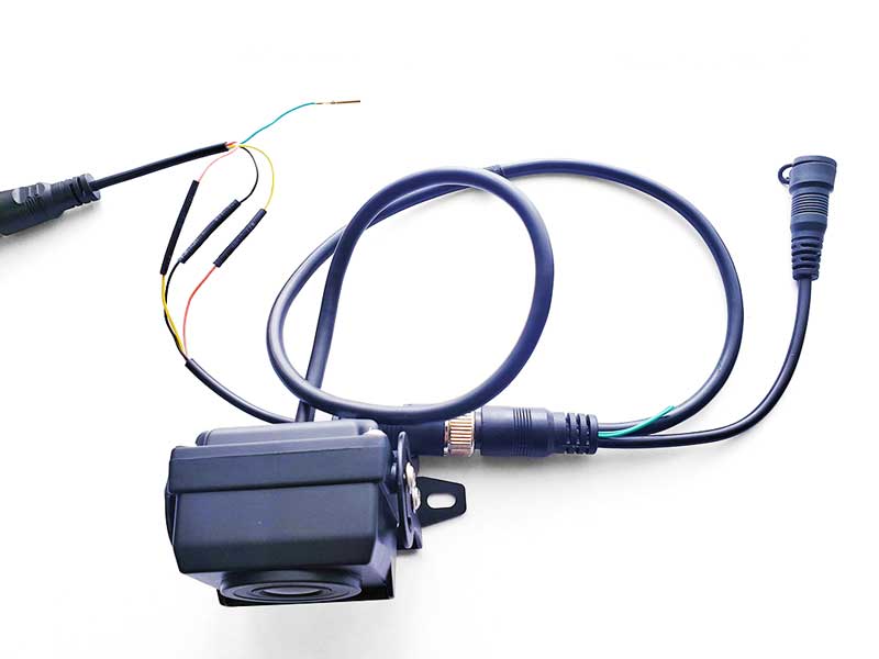
The Camera Test
Turn the vehicle to ACC, shift to reverse gear, and then test whether the camera works as expected.
Almost every vehicle, regardless of its type—whether it’s a small car, a large vehicle, a farming vehicle, an engineering vehicle, or even a ship—incorporates an ACC (Accessory) mode in its electrical system. This mode allows accessories like radios, navigation systems, and car chargers to function without starting the engine.
If your device can select the image display of a specific camera through the menu, such as Multi-Camera Display Monitors, you only need to select the target Camera display. Means no need to shift to reverse gear. Then go to Issue 2 and 3.
If the camera did not works as expected:
!!! First of all, disconnect the camera (or even all connections you can find), wait for 5 seconds, then reconnect it and test again. Sometimes, magic happens. If still not:
Issue 1: The head unit does not pop up the reverse interface.
HOW: This indicates that the head unit is not receiving the reverse trigger signal.
Case 1: If the end of the head unit’s extension cables did not come with a trigger tail cable for the reverse trigger signal, the issue may lie in incorrect wiring under the center console. Need more information? Please check this video out:
Videos for reference:
DASH CAM & BACKUP CAMERA – EASY INSTALL!! – 1980 International S1854 Dump Truck
2014 toyota sienna back up trigger wire fix for aftermarket radio instal
Honda CRV reverse camera trigger wire
Case 2: If the extension cable comes with a tail cable for the reversing trigger signal, this scenario is similar to the RCA extension cable. Click to learn about RCA wiring.
Issue 2:
Image Upside-down, Mirrored, Black and White Display, Flickering, and more…
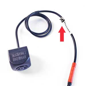
HOW: This indicates an incorrect image format. To resolve this, long-press the Format Switching Button on the camera cable for about 7 seconds until the image appears correctly. The button allows you to cycle through 10 different formats by pressing it.
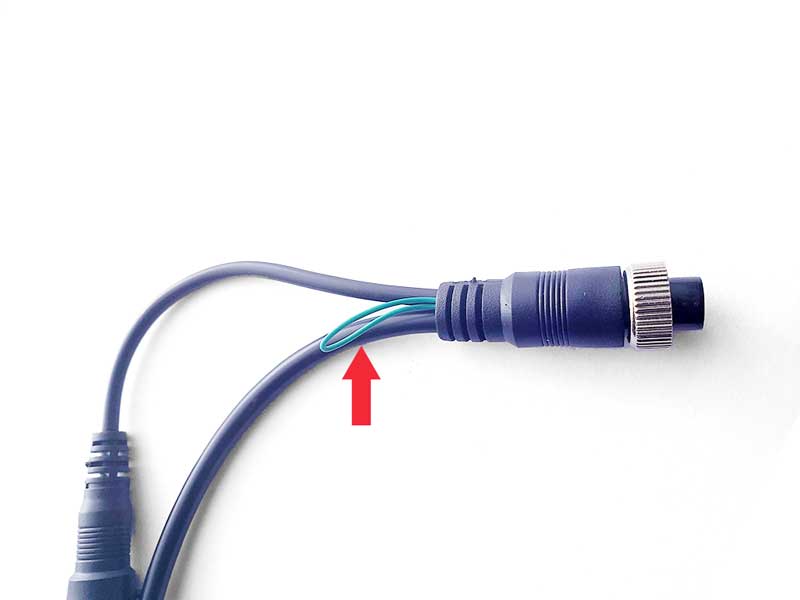
And this Green sub-cable on the camera side means to control the Guide Line. Cut this sub-cable, the Guide Line off. Re-connect it back, the Guide Line back.
Issue 3:
No Signal!
HOW: This indicates that the head unit has popped up, but there is no image signal or no correct image signal. There are some possible cases:
Case 1: Image format is incorrect.
HOW: Long-press the Format Switching Button on the camera cable for about 7 seconds until the image appears correctly. The button allows you to cycle through 10 different formats by pressing it.
Case 2: Camera was burnt out.
HOW: If there’s no image signal on the head unit after connecting the camera and the cam’s temperature rises significantly, it’s likely that the cam is burnt out. In such cases, we provide a 2nd camera in the box as replacements.
The Heavy Kit Installation Guide ends here, but if you need further assistance, please don’t hesitate to contact us.