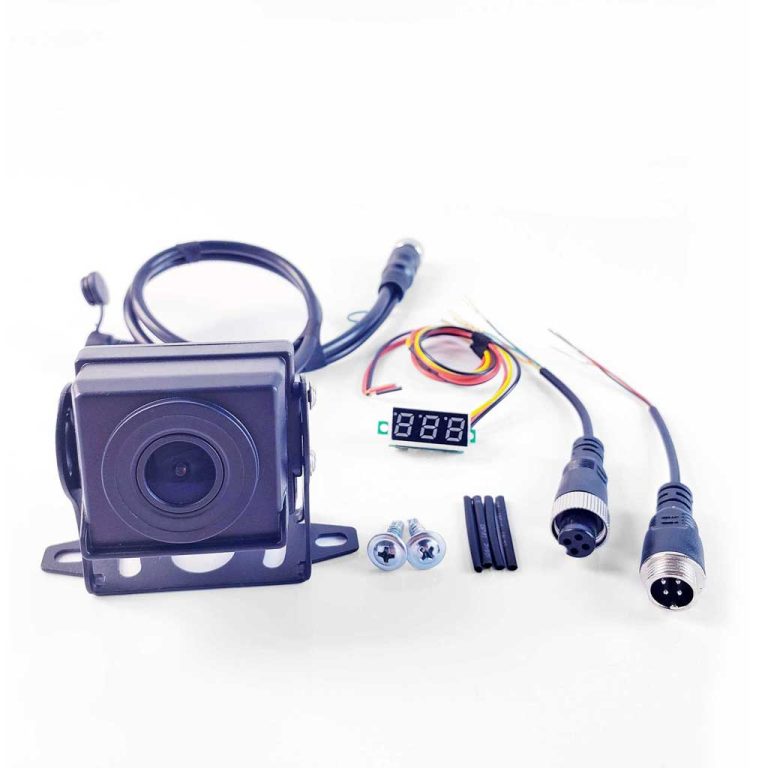


Welcome to the world of CamRescue, your ultimate solution for replacing old, defunct vehicle reversing cameras. In this guide, we’ll delve into the innovative tools designed specifically for our CamRescue series: the Cable Voltage Tester and the Cable Definition Validator.
Table of Contents
The Cable Voltage Tester Guide
The Cable Voltage Tester is an essential tool designed exclusively for our CamRescue camera kit. When replacing an old, non-functional vehicle camera, customers would face the challenge of uncertain sub-cable sequences. This specialized tester checks sub-cable voltage, empowering you to precisely identify positive, negative, and signal sub-cables for a smooth replacement process.
Components of the Cable Voltage Tester
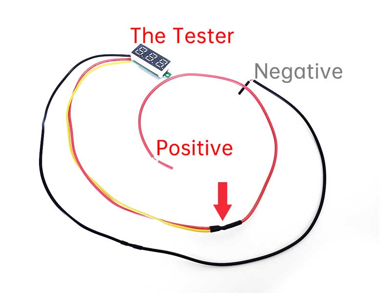
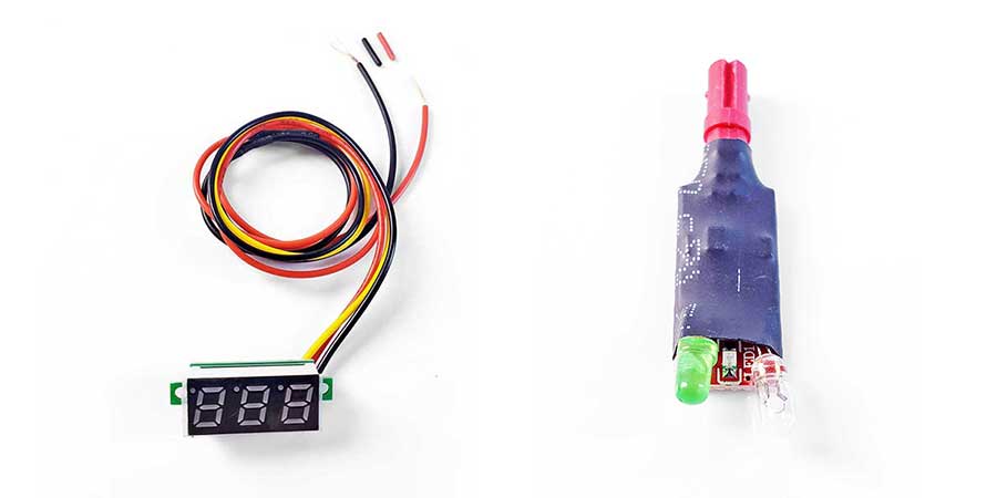
As seen in the image above, the tester comprises three fundamental components: the voltage digit display, the positive input wire (red), and the negative input wire (black).
The yellow wire is connected to the positive red wire, so for the purpose of understanding the basic components, it can be disregarded.
Guide in Brief
Step 1: Identifying the Positive Cable.
Begin by securing a reliable ground. Attach the tester’s black ground cable to it. And then connect the tester’s red cable to each sub-cable emerging from the existing extension cable to pinpoint the positive cable.
What qualifies as a good ground? Locate an exposed iron surface that’s easy to reach, like screws. Loosen the screw, fasten the wire, and then tighten it. Ensure the connection points are clean from rust and paint.
Step 2: Identifying the Negative and Signal Cables
Connect the tester’s red cable to the previously identified positive cable. Then use the tester’s black cable to individually check each remaining sub-cable from the existing extension cable. Identify the negative and signal cables based on the readings obtained.
Important Notes
Note 1: Whether you’re using our standard 4-PIN Breakout Cable or have cut the original camera cable, you’ll be dealing with individual sub-cables from the extension cable. Throughout this guide, we’ll refer to them simply as breakout sub-cables, without distinguishing between 4-PIN or factory original cables.
Note 2: It’s essential to separate each sub-cable, including those from the extension cable and the Cable Voltage Tester, to prevent a short circuit.
Note 3: Ensuring a good quality ground is crucial.
Note 4: Connect the wires with care and attention to quality.
Identify the required functional sub-cables
Before we begin, let’s establish a sample scenario and details to clarify the situation and guide you through the necessary steps quickly and effectively.
In our sample, after cutting the extension cable of the old, non-functional camera, we have six different color-coded sub-cables: black, red, yellow, brown, blue, and green. We’ll use colored dots to represent each sub-cable.
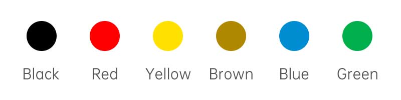
Now, let’s proceed to identify the positive sub-cable, and then, we’ll move on to identifying the negative and signal sub-cables.
Case 1: Single Voltage Below 6V
Connect the Black sub-cable of the Cable Voltage Tester to a good ground on the vehicle. Then, use the Red sub-cable to test each breakout sub-cable from the extension cable.
Regardless of whether there are 3, 4, 5, 6, or more sub-cables, if there’s only one sub-cable registering below 6V, it is the Positive sub-cable.
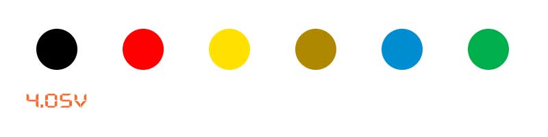
Then connect the red/positive input cable of the Cable Voltage Tester to this identified Positive sub-cable (Black) and then use the Black sub-cable of the Cable Voltage Tester to test these rest breakout sub-cables from the extension cable.
In this case, we observe that the Yellow sub-cable measures 3.33V and the Green sub-cable measures 3.22V. As the higher voltage indicates the Negative sub-cable and the lower voltage indicates the Signal sub-cable, we conclude that the Yellow sub-cable is the Negative sub-cable, while the Green sub-cable is the Signal sub-cable.
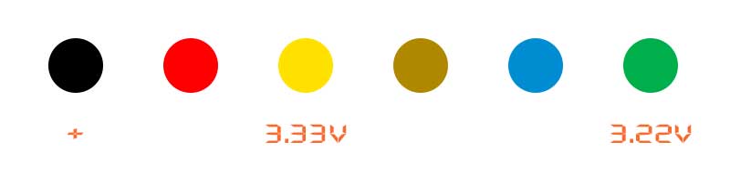
Now, connect the identified Positive (Black), Negative (Yellow), and Signal (Green) to our 4-PIN Breakout Cable (Female/Red)’s Red (Positive), Black (Negative), and Yellow (Signal) pins respectively.
And before plugging the universal camera into the 4-PIN Breakout Cable (Female/Red) for a camera test, connect the Cable Definition Validator to check if all necessary sub-cables are correctly connected.
Case 2: One Voltage Below 6V and Another Above 6V
Connect the Black sub-cable of the Cable Voltage Tester to a good ground on the vehicle. Then, use the Red sub-cable to test each breakout sub-cable from the extension cable.
Regardless of the number of sub-cables (3, 4, 5, 6, or more), if one sub-cable registers below 6V and another above 6V, the sub-cable below 6V is the Positive.
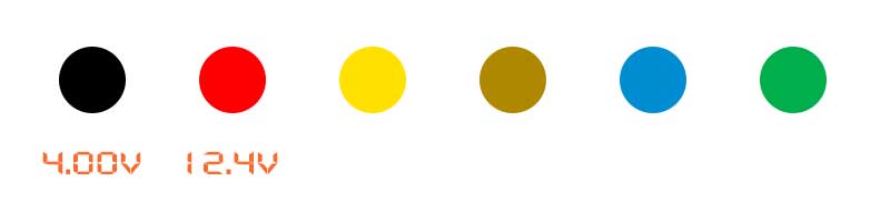
Then connect the red/positive input cable of the Cable Voltage Tester to this identified Positive sub-cable (Black) and then use the Black sub-cable of the Cable Voltage Tester to test these rest breakout sub-cables from the extension cable.
In this case, we observe that the Yellow sub-cable measures 3.33V and the Green sub-cable measures 3.22V. As the higher voltage indicates the Negative sub-cable and the lower voltage indicates the Signal sub-cable, we conclude that the Yellow sub-cable is the Negative sub-cable, while the Green sub-cable is the Signal sub-cable.
Now, connect the identified Positive (Black), Negative (Yellow), and Signal (Green) to our 4-PIN Breakout Cable (Female/Red)’s Red (Positive), Black (Negative), and Yellow (Signal) pins respectively.
And before plugging the universal camera into the 4-PIN Breakout Cable (Female/Red) for a camera test, connect the Cable Definition Validator to check if all necessary sub-cables are correctly connected.
Case 3: Single Voltage Above 6V
Connect the Black sub-cable of the Cable Voltage Tester to a good ground on the vehicle. Then, use the Red sub-cable to test each breakout sub-cable from the extension cable.
Regardless of whether there are 3, 4, 5, 6, or more sub-cables, if there’s only one sub-cable registering above 6V, it is the Positive sub-cable.
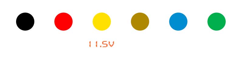
Then connect the red/positive input cable of the Cable Voltage Tester to this identified Positive sub-cable (Yellow) and then use the Black sub-cable of the Cable Voltage Tester to test these rest breakout sub-cables from the extension cable.
In this case, we observe that the Red sub-cable measures 10.7V and the Black sub-cable measures 10.3V. As the higher voltage indicates the Negative sub-cable and the lower voltage indicates the Signal sub-cable, we conclude that the Red sub-cable is the Negative sub-cable, while the Black sub-cable is the Signal sub-cable.
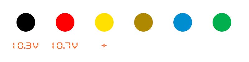
Now, connect the identified Positive (Yellow), Negative (Red), and Signal (Black) to our 4-PIN Breakout Cable (Female/Red)’s Red (Positive), Black (Negative), and Yellow (Signal) pins respectively.
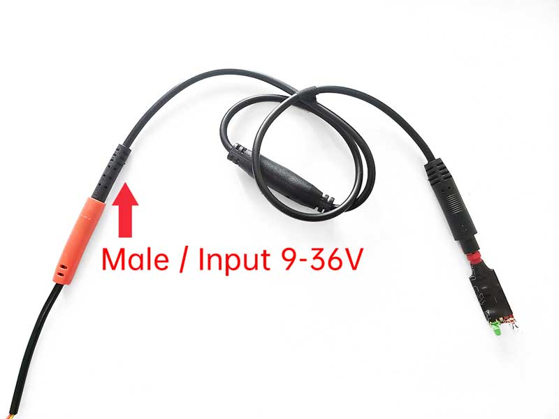
The distinction from Case 1 lies in the need for a Step-Down Cable when connecting our universal camera to the high voltage (higer then 6V) cable in this scenario.
So before plugging Cable Definition Validator to check if all necessary sub-cables are correctly connected, plugs the Step-Down Cable to the the 4-PIN Breakout Cable (Female/Red), and then connect the Cable Definition Validator to the Step-Down Cable (female side) to check if all necessary sub-cables are correctly connected.
Case 4: Two Negative Sub-Cables
Occasionally, we may encounter a situation with two negative sub-cables. In this scenario, the positive and signal cables remain determined, but the challenge lies in identifying the correct negative cable among the two possibilities.
Let’s consider Case 3 as our reference. After identifying the Yellow sub-cable as positive, we connect the red/positive input cable of the Cable Voltage Tester to this identified positive sub-cable (Yellow). Then, we use the black sub-cable of the Cable Voltage Tester to test the remaining breakout sub-cables from the extension cable.
In this case, we observe that the Red sub-cable measures 10.7V, the Green sub-cable measures 10.7V, and the Black sub-cable measures 10.3V. Since the higher voltage indicates the negative sub-cable and the lower voltage indicates the signal sub-cable, we conclude that the Red and Green sub-cables are both potential negative sub-cables, while the Black sub-cable is definitely the signal sub-cable.
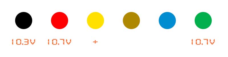
Now, we need to experiment to determine the correct negative sub-cable. And the method is simple: try one by one.
Try the Red one: Connect the identified Positive (Yellow), the Potential Negative (Red), and the Signal (Black) to our 4-PIN Breakout Cable (Female/Red)’s Red (Positive), Black (Negative), and Yellow (Signal) pins respectively.
Then plugs the Step-Down Cable to the the 4-PIN Breakout Cable (Female/Red), and then connect the Cable Definition Validator to the Step-Down Cable (female side) to check if all necessary sub-cables are correctly connected. If the Cable Definition Validator provides accurate feedback, then the Red sub-cable is the right Negative.
If the Cable Definition Validator provides incorrect feedback: Try the Green one.
Test the Green sub-cable in the same manner as you did with the Red one. If the Cable Definition Validator provides accurate feedback in this case, then the Green sub-cable is the correct Negative.
If the Cable Definition Validator provides incorrect feedback in the case of both the Red and Green sub-cables, connect the Red and Green together as the potential Negative. Then, retry the process.
In one of these cases, you will find the correct Negative.
If you encounter a Positive voltage lower than 6V, the Step-Down Cable is not required in your case.
The Cable Definition Validator Guide
The Cable Definition Validator is an essential tool designed exclusively for our CamRescue camera kit. Once the sub-cable identification work is completed and the 4-PIN Breakout Cable is connected with the identified sub-cables, the Cable Definition Validator serves as a tool to test the accuracy of our identification and wiring work.
When the Cable Definition Validator provides the right feedback, it gives us the utmost confidence to plug the universal camera in and turn the vehicle on.
Components of the Cable Definition Validator
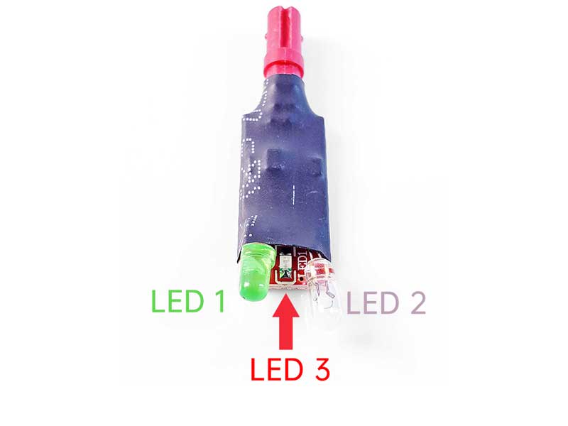
As shown in the image above, all you need to know about the Validator are these three LED lights. Different combinations of LED lights represent different signals for you.
3 Light Signals and Their Meanings
There are 3 different light combination signals, they are:
- PASS: LED 1 and LED 2 light up, while LED 3 remains unlit
- Wiring Error: Only one of LED 1 or LED 2 lights up, while LED 3 remains unlit
- Voltage is too high: LED 3 lights up
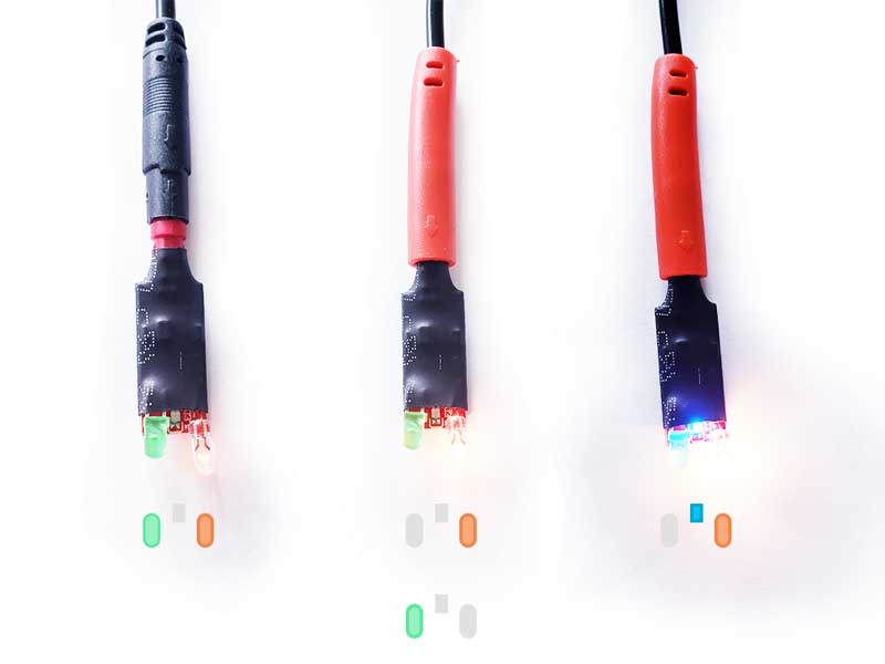
If the light signal indicates PASS, proceed by removing the Cable Definition Validator and plug in the universal camera for a camera test.
If the light signal indicates Wiring Error, first check the wiring or use the Cable Voltage Tester to re-identify the correct Positive, Negative, and Signal sub-cables.
If the light signal indicates Voltage is too high, utilize the Step-Down Cable as necessary.
Check power supply by using Cable Voltage Tester or Cable Definition Validator
Tools are an expression of human creativity.
Check power supply by using Cable Voltage Tester
When using the Cable Voltage Tester to check the sub-cables, a voltage reading between 3-36V indicates a normal power supply.
If no voltage value can be measured, it suggests a potential issue with the power supply. In such cases, it’s advisable to inspect the entire extension cable and the connection with the head unit to confirm and address the problem.
Check power supply by using Cable Definition Validator
When encountering an RCA connector and needing to check for power supply from the extension cable, connect the CVBS RCA Adapter to the RCA connector and then plug in the Cable Definition Validator. If the LED lights illuminate, it indicates a power supply.
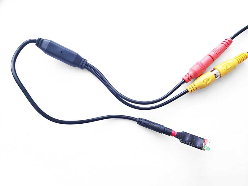
If the LED lights do not illuminate, it suggests a potential issue with the power supply. In such cases, it’s recommended to inspect the entire extension cable, wiring, and the connection with the head unit to confirm and address the problem.