

This Universal Kit Installation Guide is the step by step installation tutorial of CamRescue – Universal Kit, you can visit CamRescue to choose the product you need to buy.
Table of Contents
Why We Call it Universal Kit
As CamRescue provides universal cameras for replacing dead vehicle cameras, you might wonder about why there is a single kit named Universal Kit. The answer is simple. This kit not only offers multiple formats but also works seamlessly with different connectors. Whether it’s an RCA connector, a dash cam 4-PIN connector, or an original factory connector, this kit does the job. That’s why we named it the Universal Kit.
In other words, when you need to fix your vehicle’s dead backup camera but aren’t sure about the old cam’s specs, this kit is the solution.
For certain connector dead cameras, please choose:
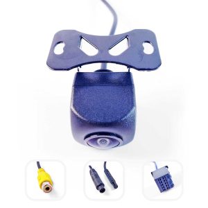

Front-Back Kit
Front or Back Cameras for 360 Bird-View Systems
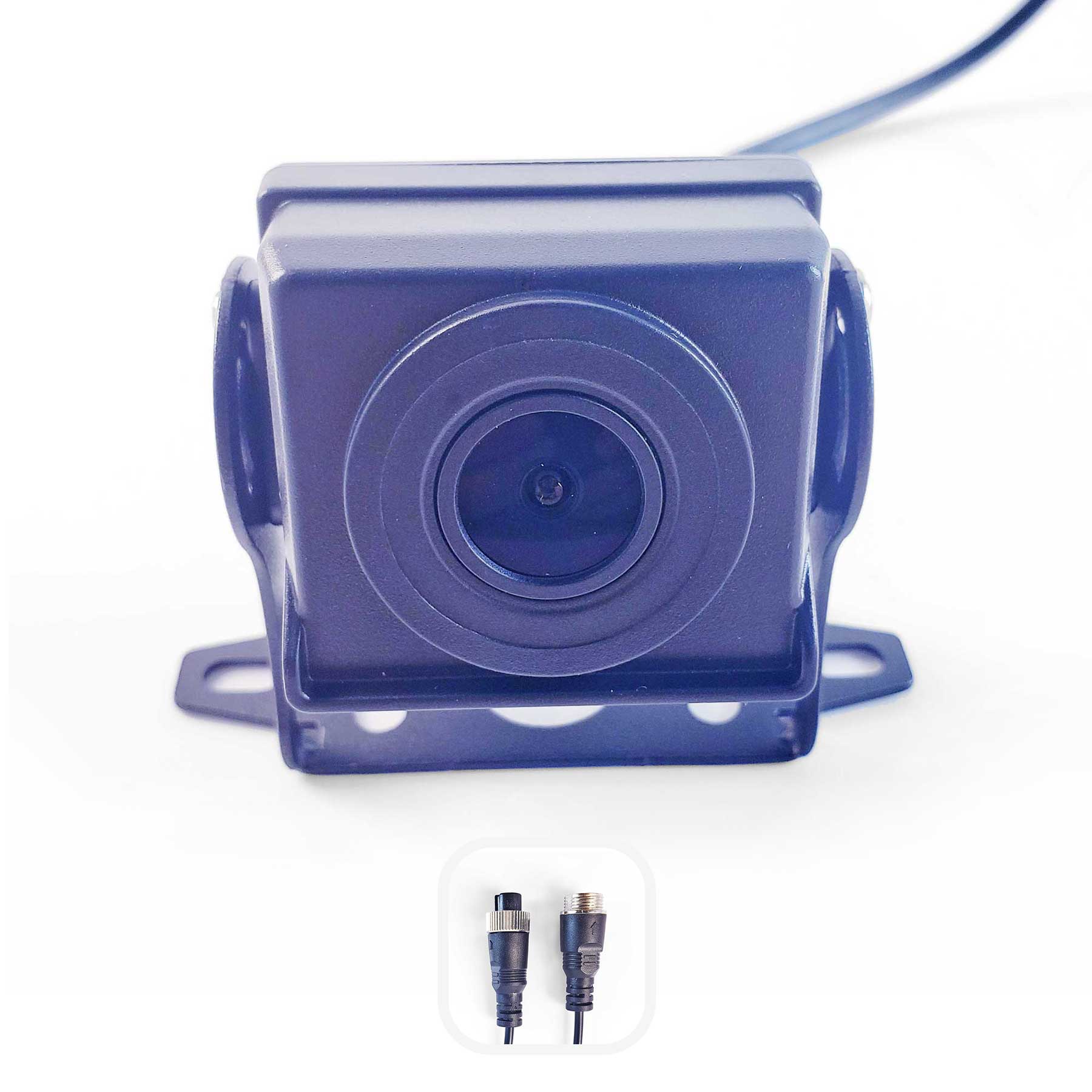
Heavy Kit
Backup or Side Cameras for Heavy Vehicles
Inside the Box
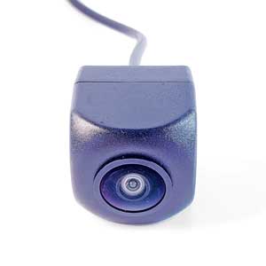
The Universal Camera: The universal camera included in the kit, featuring a pre-equipped dash cam 4-pin male connector. A physical format switching button in the middle of the cable allows you to switch to the next format by long-pressing for about 7 seconds.
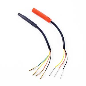
4-PIN Breakout Cable (Male/Black): A dash cam 4-PIN male connector that converts to four separate sub-cables (with pins).
4-PIN Breakout Cable (Female/Red): A dash cam 4-PIN female connector that converts to three separate sub-cables (with pins).
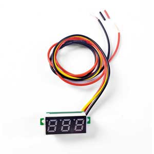
Cable Voltage Tester: Use this voltage tester to identify the correct power supply cable among the sub-cables.
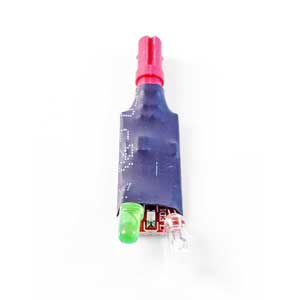
Cable Definition Validator: The LED lights on this indicator inform you whether the sub-cable sequence (DC input) is correct or not.
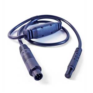
Step-Down Cable: This cable steps down 5V to 36V input to a 5V output. Use this step-down cable when the power input of your device is higher than 5V.
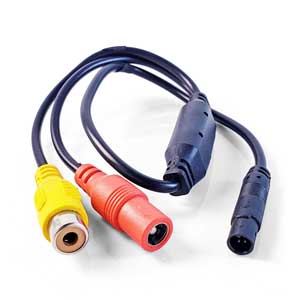
CVBS RCA Adapter: Pre-equipped with a dash cam 4-PIN female connector, this adapter can plug directly to the Universal Camera, transforming it into an RCA connector camera. With a female DC power plug, paired with the DC Power Connector.
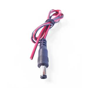
DC Power Connector: Use this cable with the CVBS RCA Adapter when there’s no DC power supply from the RCA cable. Find and connect an external 5V to 36V DC input, and plug it to the CVBS RCA Adapter if necessary.
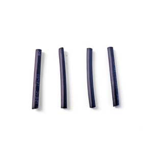
Heat Shrink Tubes: Used to protect the joints of the 4-PIN Breakout Cable. Heating causes them to shrink.
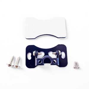
Backup Camera Mount (Adjustable): The angle adjustable camera mount. Tighten the camera to the mount with screws B.
Double-Sided Tape: Used as an optional method to fix the camera mount to the car.
Screws A x2: Used as an optional method to fix the camera mount to the car.
Screws B x2 (the smallers): Used to tighten the universal camera to the mount.
Good to Know Before Installing
A. Which side is the upper side?
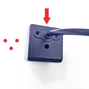
① Two holes for tightening. It is the upper side.
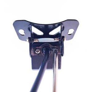
② So this is how we install the mount.
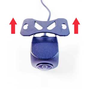
③ Correct direction when installing to car
B. Fool-proof design on dash cam 4-PIN connector.
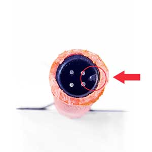
① Cut to show the fool proof design inside 4-PIN connector
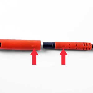
② So align these two arrows together when connecting
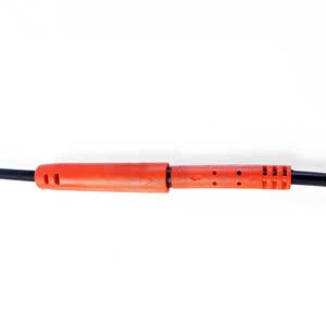
③ Dash cam 4-PIN connector well connected
Are there a fool-proof desgin in the RCA connector? No, it’s just a plug and play game.
C. No standardized PIN/sub-cable sequence for 4-PIN connectors in the market.
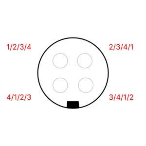
For unsure situation, use the Cable Voltage Tester to confirm the sequence—inserting connectors recklessly may damage the camera, main unit, or even the vehicle’s electrical system. Play the 4-PIN connector plug-and-play game only after confirming the sequence.
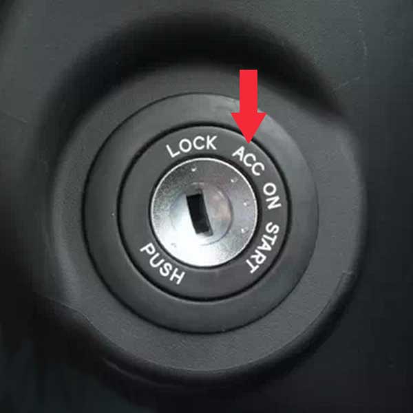
D. Turning the key to ACC mode powers the head unit without starting the vehicle.
E. The vehicle can be shifted into reverse gear with the key in ACC mode and the handbrake engaged.
Choose Your Case of Installing
① Ideally, it’s better to ensure that the extension cable from the head unit is still functional before investing time in replacing the camera.
② When connecting the wires, the car needs to be turned off.
Check the connector type of your vehicle’s host device extension cable and click to go to the correct tutorial.
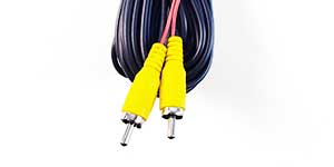
RCA
Cable ends with RCA connector.
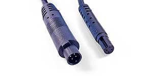
4-PIN
Cable ends with dash cam 4-PIN connector.
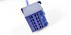
Factory Original
Cable ends with original factory connector.
RCA Installing
After removing the dead old camera, if you discover that the car’s backup camera is equipped with an RCA connector, great—it’s a plug-and-play game now.
Step 1:
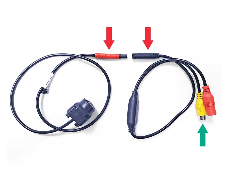
Take our universal camera and the RCA adapter. Connect them following the picture below. Pay attention to the 4-PIN fool-proof design.
Step 2:
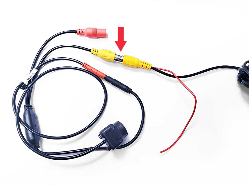
Plug the RCA connector into the extension cable connected to the head unit.
Step 3:
Test the Camera System.
A). Turn the car to “ACC” mode.
B). Shift the shifter to Reverse gear.
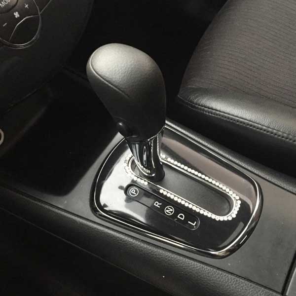
How to shift to Reverse gear on ACC?
① Step on the brake pedal
② Shift to reverse with the handbrake up
C). Now, the rearview camera system should be active.
!!! First of all, disconnect the camera, wait for 5 seconds, then reconnect it and test again. Sometimes, magic happens. If still not:
Issue 1:
The head unit does not pop up the reverse interface.
HOW: This indicates that the head unit is not receiving the reverse trigger signal.
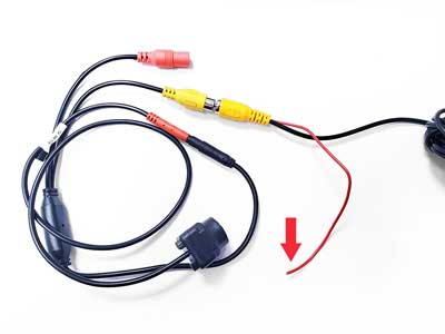
If your head unit previously displayed the reverse interface while reversing, connect the tail cable (as shown in the picture) along with the DC Power Connector’s red sub-cable to the reverse light’s positive 12V cable.
If the head unit never displayed the reverse interface, connect the tail cable (as shown in the picture) along with the DC Power Connector’s red sub-cable to the reverse light’s positive 12V cable and try to shift to reverse gear and check again. If it still doesn’t pop up, check if the head unit’s reverse trigger cable is correctly connected to the tail cable on the head unit side, or the fuse box, or another source providing a reversing signal.
Issue 2:
Image Upside-down, Mirrored, Black and White Display, Flickering, and more…
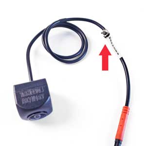
HOW: This indicates an incorrect image format. To resolve this, long-press the Format Switching Button on the camera cable for about 7 seconds until the image appears correctly. The button allows you to cycle through 10 different formats by pressing it.
Issue 3:
No Signal!
HOW: This indicates that the head unit has popped up, but there is no image signal or no correct image signal. There are some possible cases:
Case 1: Image format is incorrect.
HOW: Long-press the Format Switching Button on the camera cable for about 7 seconds until the image appears correctly. The button allows you to cycle through 10 different formats by pressing it.
Case 2: Camera has no power supply.
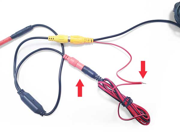
HOW: Connect the tail cable (as shown in the pic) along with the DC Power Connector’s red sub-cable to the vehicle’s reverse light’s positive 12V cable, shift to reverse gear and check again. Or use Cable Definition Validator for power check.
Case 3: The negative cable was not correctly grounded.
HOW: Ensure the ground wire cable is connected to a bare metal surface. And then try to test the rear view system again.
Case 4: The extension cable from the head unit is damaged.
HOW: Worst case scenario, you’ll need to overhaul your wiring.
Case 5: Camera was burnt out.
HOW: Our CVBS RCA Adapter includes a voltage step-down function, minimizing the chances of camera burnout. To confirm, connect the camera to the TV’s RCA port for testing. In burnt out cases, we indeed have provided a 2nd camera in the box as replacements.
Want to learn more about wiring? Check these informative video out:
Video for reference:
How to wire reverse camera if your vehicle has canbus
If the problem persists or if you require further assistance, please do not hesitate to contact us.
4-PIN Installing
Guide in Brief:
- Connect the 4-PIN Breakout Cable (Male/Black) to the 4-PIN extension cable’s connector.
- Use the Cable Voltage Tester to confirm the function of the 4-PIN Breakout Cable’s pins.
- Connect the positive to the red sub-cable, negative to the black sub-cable, and the signal to the yellow sub-cable on the 4-PIN Breakout Cable (Female/Red).
- Connect the camera to the 4-PIN Breakout Cable (Female/Red).
When dealing with a dash cam 4-PIN connector after removing the old, dead camera, the process becomes a bit more involved than a simple plug-and-play game. However, you’re still in control.
With uncertain pin definitions in each case, the Cable Voltage Tester becomes the key tool for success.
If the extension cable’s connector differs from the tutorial, follow these steps: Cut the old cable of the dead camera, separate the sub-cables, and reconnect it to the head unit’s extension cable. Test each sub-cable, identifying the Positive, Negative, and Signal. Connect them to the 4-PIN Breakout Cable (Female) accordingly. Red to positive, black to negative, and yellow to signal.
Step 1:
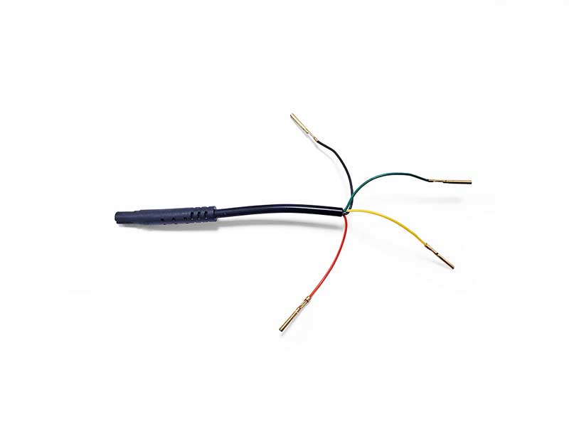
Separate each sub-cable before plugs the 4-PIN Breakout Cable (Male/Black) into the 4-PIN connector.
Step 2:
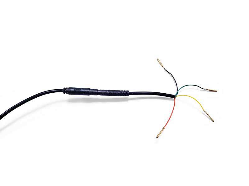
Connect the 4-PIN Breakout Cable (Male/Black) to the 4-PIN extension cable’s connector.
Step 3:
Use the Cable Voltage Tester to confirm the definition of the 4-PIN Breakout Cable’s pins.

In this case, we confirm that the yellow wire functions as the positive cable.
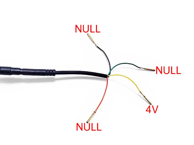
And then, we have the black wire = 3.3V, the red wire = 3.2V and the green wire = NULL.
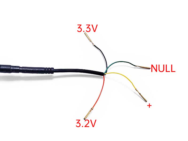
According to the usage guide of Cable Voltage Tester, we can know that the balck wire is the positive cable, the red wire is the signal cable, and the green wire is of no use to us.
Cable Voltage Tester Guide
Step-by-step tutorial for confirming voltage and function of each sub-cable.
Step 4:
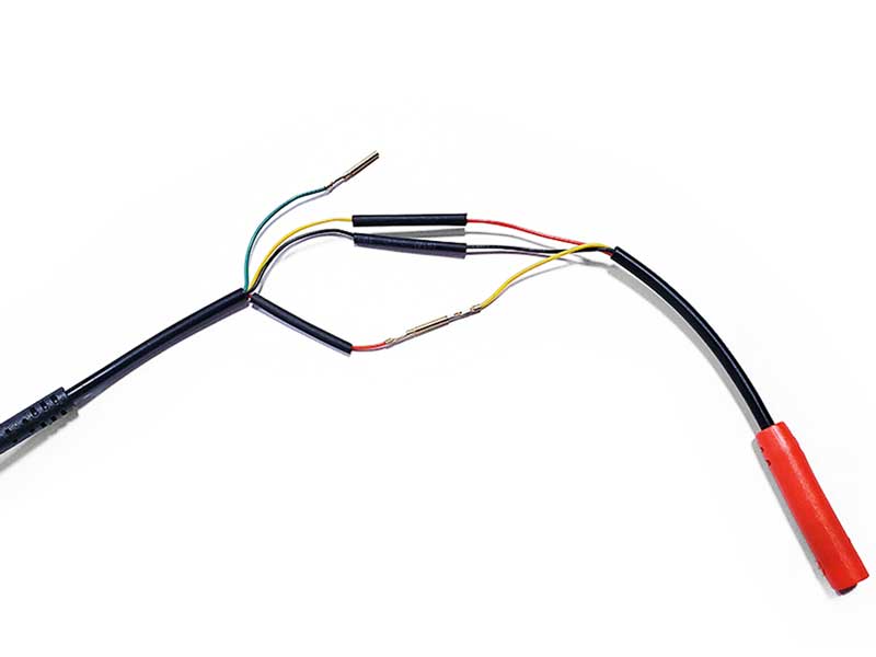
Connect the positive to the red sub-cable, negative to the black sub-cable, and the signal to the yellow sub-cable on the 4-PIN Breakout Cable (Female/Red).
Exercise caution while wiring to prevent wires from touching. Use heat shrink tubing to shield them from unintended contact.
Step 5:
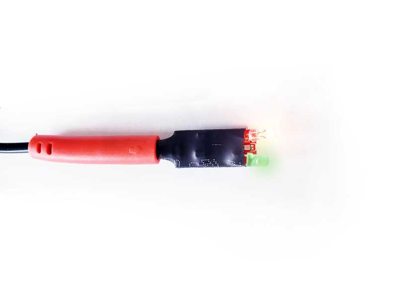
Connect the Cable Definition Validator to the 4-PIN Breakout Cable (Female/Red) to verify the correct confirmation of subcables.
Cable Definition Validator Guide
Know exactly what each warning light means.
If you encounter warning lights from the Cable Definition Validator, go back to Step 3 and ensure the correct definition of the sub-cables.
In our case, we have correctly connected the sub-cables and pins.
Step 6:
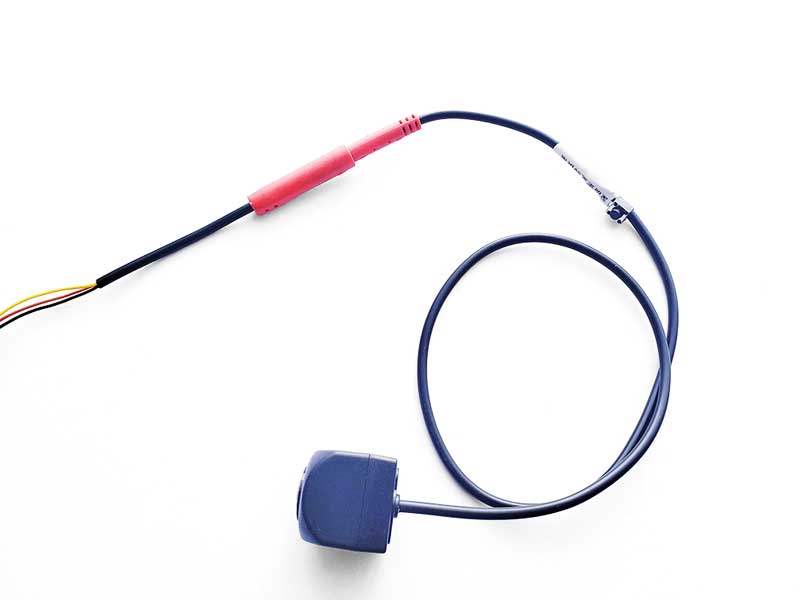
Now that we have correctly connected the sub-cables and pins, let’s plug the universal camera into the 4-PIN Breakout Cable (Female/Red) and check if the camera works as intended.
Step 7:
Camera Test! Turn the car to ACC, shift to reverse gear, and then test whether the camera works as expected. If not:
!!! First of all, disconnect the camera(or even all connections you can find), wait for 5 seconds, then reconnect it and test again. Sometimes, magic happens. If still not:
Issue 1: The head unit does not pop up the reverse interface.
HOW: This indicates that the head unit is not receiving the reverse trigger signal.
Case 1: If the end of the dash cam 4-PIN extension cables did not come with a trigger tail cable for the reverse trigger signal, the issue may lie in incorrect wiring under the center console. Need more information? Please check this video out:
Videos for reference:
2014 toyota sienna back up trigger wire fix for aftermarket radio instal
Honda CRV reverse camera trigger wire
Case 2: If the extension cable comes with a tail cable for the reversing trigger signal, this scenario is similar to the RCA extension cable. Click to learn about RCA wiring.
Issue 2:
Image Upside-down, Mirrored, Black and White Display, Flickering, and more…
HOW: This indicates an incorrect image format. To resolve this, long-press the Format Switching Button on the camera cable for about 7 seconds until the image appears correctly. The button allows you to cycle through 10 different formats by pressing it.
Issue 3:
No Signal!
HOW: This indicates that the head unit has popped up, but there is no image signal or no correct image signal. There are some possible cases:
Case 1: Image format is incorrect.
HOW: Long-press the Format Switching Button on the camera cable for about 7 seconds until the image appears correctly. The button allows you to cycle through 10 different formats by pressing it.
Case 2: Camera was burnt out.
HOW: Connect the CVBS RCA Adapter and verify its performance on the TV’s RCA port. Or in burnt out cases, we indeed have provided a 2nd camera in the box as replacements, use it.
If you need further assistance, please don’t hesitate to contact us.
Original Factory Connector Installing
If you’re dealing with the factory OEM connector of the old dead camera, first, clarify why you’re opting for our CamRescue universal cameras. Perhaps you want a hassle-free solution without rewiring extensively, which could be a significant task and risk damaging components in your old vehicle.
The good news is that the Original Factory Connector Installation is like the same game as the 4-PIN Installation. The key differences are: firstly, you need to cut off the old cable to access the sub-cables, and secondly, there might be more than 3 or 4 sub-cables—potentially 5, 6, or 7. Regardless of the quantity, your goal is to identify the positive, negative, and signal sub-cables, leaving the others untouched.
There are numerous types of original car connectors, but the repair process remains consistent, regardless of the specific connector type.
Step 1:
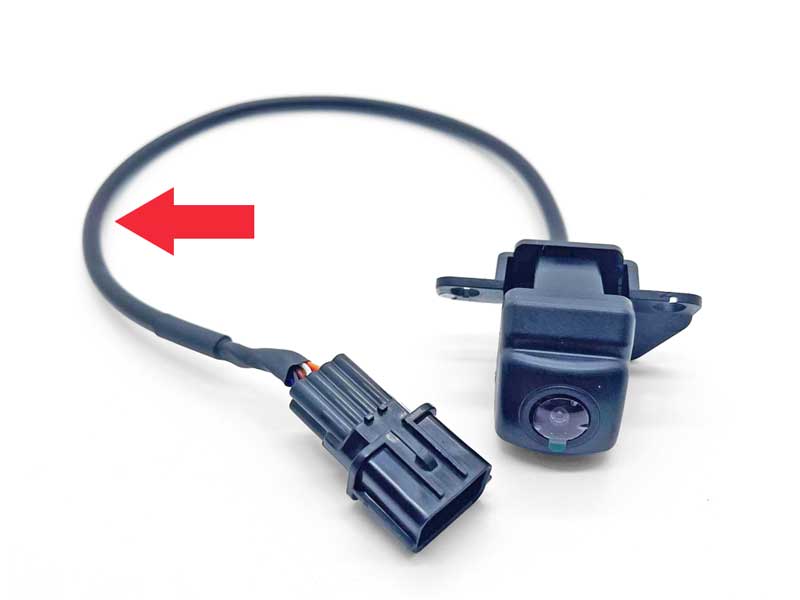
When you remove the old, dead camera from the vehicle, cut the cable approximately 10cm near the connector, as indicated in the image.
Step 2:
After cutting off the cable, separate all the sub-cables. Reconnect the plug to the factory male or female connector. Then, use the Cable Voltage Tester to identify the positive, negative, and signal sub-cables required, leave the rest, no matter how many there are, alone. In our case it’s 5 sub-cables.
DO ensure that the unused sub-cables are individually wrapped with electrical tape to prevent any potential short circuits.
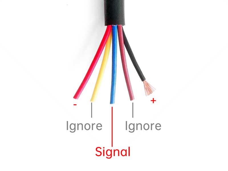
Step 3:
The remaining steps are the same as Step 4 of the 4-PIN installation process, involving connecting the sub-cables and pins, and testing the camera system. Click to to 4-PIN Installing Step 4 now.
FAQ
Q: Can I set the vehicle to reverse gear without starting the engine?
A: Certainly! You can set the vehicle to reverse gear without turning the engine on. Turn the key to ACC mode, or if it’s a start button system, press the ignition without applying brakes. For more information, you can also check YouTube or Google by searching for “Accessory Mode” and your brand and model.
Q: Can I access the reversing image on the head unit through the menu instead of shifting the vehicle into reverse gear?
A: It’s uncertain. Various head units, brands, models, and software versions come with different menus and settings. For specific information, reach out to your head unit’s seller or search online for instructions on how to access the reversing image for your specific head unit brand and model.
There are potential menu navigation guides for your reference on Android head units, but we cannot guarantee they will work on your specific device precisely:
- Factory settings → Parameter settings → Reversing clarity
- Car settings → Factory settings → Camera settings → Reverse setting → Camera format settings
Some commonly used passwords to access Factory settings are: 1617, 8888, 3368, 0000, 888888, 1111, 6666, 0000, 123456…
Q: Where can I find a suitable ground for the negative cable?
A: Look for any exposed iron surface that is easily accessible, such as screws. Loosen the screw, connect the wire to it, and then tighten the screw. The connection points need to be free of rust and paint.
Q: How can I determine if my existing extension cable is in good condition?
A: Our Cable Voltage Tester can help with that. When you use it to identify the right positive sub-cable and find voltage, it indicates the positive cable is good. Similarly, checking for the negative and signal sub-cables will determine the condition of those specific cables. If only one sub-cable shows voltage on the tester, or if there’s no voltage at all, it suggests the extension cable may be damaged.
Q: What should I do if my existing extension cable is broken?
A: Well, you’ll need to re-wire a new and good one.
Q: What should I do if the aftermarket head unit’s extension cable connector is 5-PIN/unknown/different size?
A: It’s similar to our Original Factory Connector Installing guide. Cut the old camera’s cable and connect the sub-cables of the old connector with our 4-PIN Breakout Cable. Connect the old connector back and proceed with the rest of the steps as outlined in the 4-PIN Installing guide.
Q: What should I do if the extension cable’s connector is male that not same as shown in this tutorial?
A: Cut the extension cable of the old, non-functional camera, use the connector side and separate each sub-cable. Reconnect it to the existing extension cable, and proceed to test each separated sub-cable to identify the correct Positive, Negative, and Signal cables. Once identified, connect them correctly to the 4-PIN Breakout Cable (Female/Red). You should have the red pin connected to the positive sub-cable, the black pin to the negative sub-cable, and the yellow pin to the signal sub-cable. And this is the key.
Q: If I incorrectly connect the sub-cables, could it damage my head unit?
A: Yes, it could.
If you cannot use the Cable Voltage Tester to identify at least the positive sub-cable, avoid connecting the universal camera haphazardly. Follow our Cable Voltage Tester Guide to identify the positive sub-cable and then the negative and signal sub-cable, and use our Cable Definition Validator to ensure all connections are correct.
If the system continues to malfunction, switch between formats, reconnect all the connectors, and power up the system again. If, despite these efforts, the reversing camera system still doesn’t function correctly, you can experiment with different ground or signal sub-cable connections. If uncertain, it’s recommended to search for details about your head unit and the extension cable on the internet or seek professional local mechanicians.